Introduction: The Overlooked Electrical Criterion
Most proximity sensor selection conversations begin — and often end — with sensing distance, housing size, mounting style and output type. Voltage drop is rarely on the shortlist, until a machine behaves erratically at the end of a long cable run or a two-wire sensor cannot fully release a PLC input. Voltage drop sits at the intersection of sensor electronics, wiring, load characteristics and control-system thresholds. Evaluating it during specification is considerably less expensive than diagnosing it during commissioning.
What Voltage Drop Actually Means in a Sensor Circuit
Voltage drop is the reduction in electrical potential between the power supply and the point where the sensor and its load truly operate. Conductors, connectors, terminal blocks, contacts and any series elements between the supply and the sensor each consume part of the available voltage. What governs reliable switching is the voltage present at the sensor and its output stage at the instant of switching — not the nominal figure printed on a datasheet.
The Supply Path and the Load Path
Two distinct circuits deserve separate attention. The supply path delivers operating voltage to the sensor’s internal electronics. The load path carries the switched current to whatever the sensor controls — a PLC input, a relay, a control cabinet circuit or an automated machine input. Deficiencies in the supply path can cause unstable oscillation and missed detections; deficiencies in the load path can cause incomplete switching, weak logic levels or false triggering of the receiving device. Mapping both paths separately prevents the common mistake of treating voltage drop as a single, uniform quantity.
Two-Wire and Three-Wire Behavior
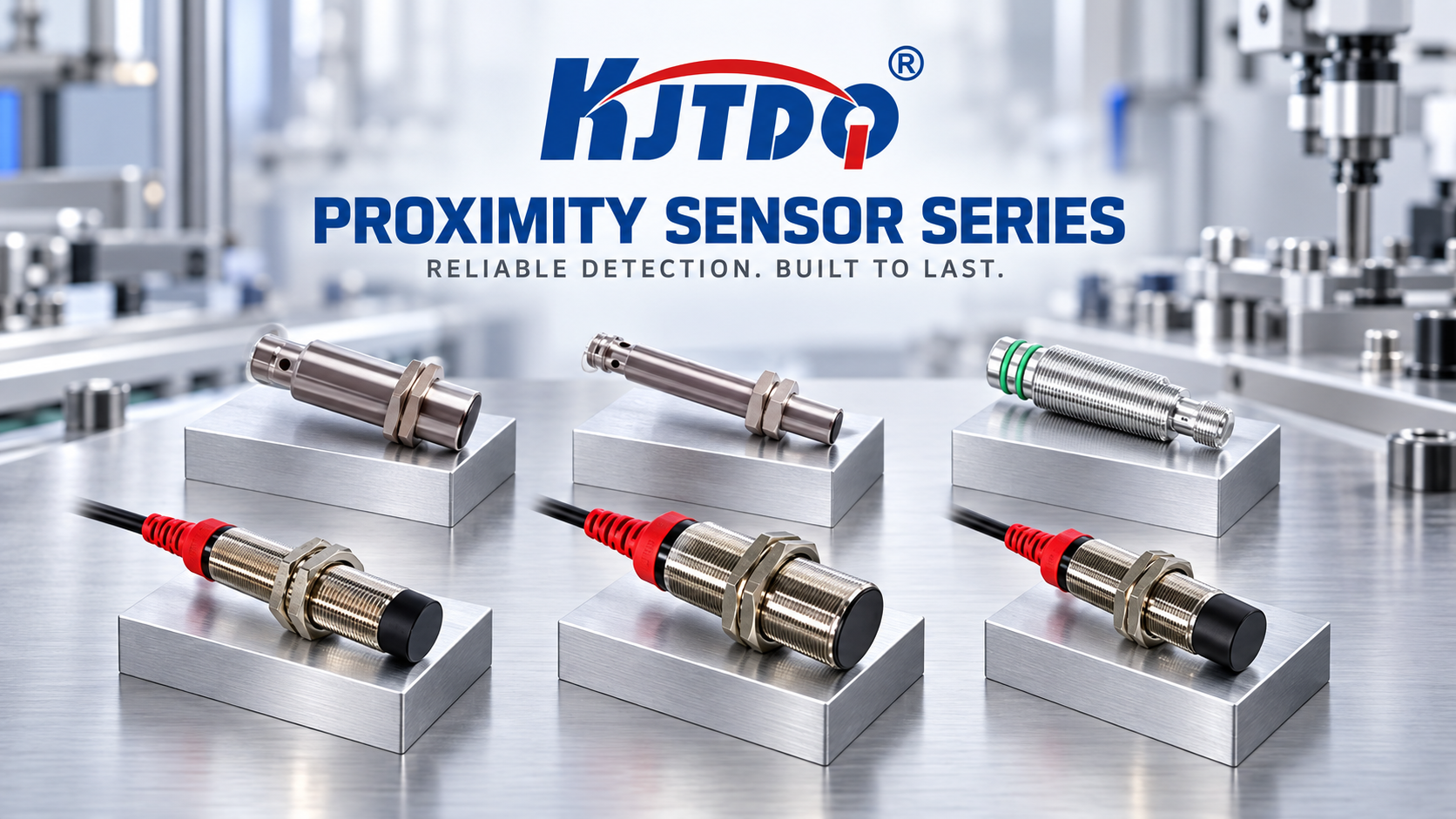
The practical consequences of voltage drop differ sharply between wiring configurations. In a three-wire sensor, supply and load paths are largely separate: the sensor draws its operating current through the supply pair and switches the load through the output conductor. In a two-wire configuration, the sensor’s own operating current flows through the same loop as the load, so the relationship between leakage current, load impedance, remaining voltage across the sensor and the threshold of the receiving input becomes considerably more sensitive. This is why correct selection between two- and three-wire versions — alongside NPN or PNP — is presented as an integration decision rather than a formality.
Factors That Determine Voltage Drop
- Operating voltage and its tolerance. The higher the nominal supply, the more absolute headroom exists before thresholds are threatened, but the tolerance band must be respected.
- Load current. Higher switched current increases the drop across every resistive element in the loop.
- Cable length and conductor cross-section. Longer runs and smaller conductors increase resistance and therefore drop.
- Connectors and terminations. Each cable/connector interface and terminal point adds resistance.
- Series elements. Relays, junction boxes, terminal blocks and barriers all sit in the path.
- Output configuration. NPN or PNP, normally open or normally closed, and analogue output variants each present different electrical loading.
- Ambient temperature. Conductors and electronics behave differently at elevated temperature; temperature compensation and protection circuits address part of this, but the wiring budget still deserves review.
- Switching frequency and duty cycle. Continuous, high-frequency switching keeps the circuit under sustained load rather than in a quiescent state.
How to Evaluate Voltage Drop Step by Step
- Define the real supply. Establish the actual voltage delivered at the panel, not the ideal value, and account for its tolerance band.
- Establish the load. Identify the receiving device — PLC input, relay, control circuit — and the current it demands.
- Map the complete loop. Count every metre of cable, every connector, every terminal and every series device between the supply and the load.
- Check the switching thresholds. Confirm that the receiving input will still recognise both the ON and the OFF state once drop is subtracted.
- Reconcile with the output configuration. Verify that the chosen NPN/PNP and two- or three-wire arrangement behaves acceptably under the worst-case load.
- Test the worst case, not the average. Evaluate at maximum cable length, maximum load current, minimum supply tolerance and maximum ambient temperature together.
- Confirm the margin with the supplier. Because operating voltage, cable or connector type, and output configuration are quoted parameters, the selection dialogue is the natural point to validate the voltage budget.
Where Inductive and Capacitive Sensors Differ
Inductive proximity sensors detect metal targets through electromagnetic induction: the sensing face builds an alternating electromagnetic field, a metal target produces eddy currents and changes oscillation, and that change is converted into a switching output. They are non-contact and wear-free, with high switching frequency and high detection accuracy — characteristics that make them suited to position, presence, limit, counting and end-of-travel applications.
Capacitive sensors form a capacitor between the sensing face and the surrounding environment; an approaching target changes the dielectric constant and capacitance, which is processed through oscillation, filtering, amplification and threshold evaluation into a switching signal. They detect metals and non-metals — liquids, powders, granules, plastics, glass, wood, paper and rubber — including indirectly through non-metallic container walls, and they operate independently of ambient light.
Both families offer NPN, PNP and other switching outputs for connection to a PLC, relay, control cabinet or automated machine, so the voltage-drop evaluation follows the same logic in each case; the difference lies in the signal-processing chain and the load the receiving circuit presents.
Voltage Drop in Demanding Environments
In high-temperature, high-pressure, corrosion-prone or weld-spatter-exposed installations, protection ratings and material selection are usually the headline topics — yet the electrical loop still has to close. Shielded construction, temperature compensation and protection circuits reduce electromagnetic interference, temperature drift, short-circuit and reverse-polarity risk, and they improve the reliability of the switching signal that must survive the voltage budget. In explosion-hazardous areas, a standard proximity switch is not appropriate; intrinsically safe NAMUR or another suitably certified explosion-proof product must be selected and configured according to the site’s explosion-protection requirements, and the associated loop arrangement should be reviewed alongside the voltage evaluation.
Why Configuration Data Belongs in the Quotation
KJT Sensors quotes inductive proximity sensors according to product series, enclosure dimensions, sensing distance, mounting and output configuration, cable or connector type, operating voltage, IP rating, temperature rating, explosion-protection, corrosion and weld-spatter resistance, wireless or analogue requirements, order quantity and customisation. Capacitive sensors are quoted by model, sensing distance, appearance specifications, mounting method, output type, operating voltage, IP rating and sensitivity adjustment method. Because operating voltage and cable/connector type sit explicitly in that list, standard models can be quoted quickly once model and quantity are known, while special-environment and non-standard designs benefit from a technical review of site conditions and the control-system interface.
A Practical Checklist for Specifying Engineers
- Confirm the actual supply voltage and its tolerance at the installation point.
- Determine the load current and the input threshold of the receiving device.
- Total up cable length, conductor size, connectors and series elements.
- Select NPN or PNP, and two- or three-wire, against the PLC input type and field wiring.
- Match sensing distance and target material to the application.
- Review temperature rating, IP rating and explosion-protection requirements together with the electrical budget.
- Validate the worst-case combination before finalising the order.
Conclusion
Voltage drop is a selection criterion, not a commissioning surprise. Engineers who treat the supply path, the load path, the wiring configuration and the receiving input as one system — and who settle those questions at specification stage — arrive at proximity sensors that switch cleanly for the life of the machine. KJT Sensors supports that process by quoting against operating voltage, output configuration, cable or connector type and environmental rating, so the electrical margin and the mechanical envelope are resolved in the same conversation.
https://www.kjt-sensors.com/
KJT Sensors